--> Delphi Tips Trick: Parallel Port / LPT Port / Printer Port Delphi | Deskripsi Singkat Blog di Sini

For Newbie

Showing posts with label Parallel Port / LPT Port / Printer Port Delphi. Show all posts

Friday, 28 October 2011

Register Address on Parallel Port

Register Address on Parallel Port

    all pin of parallel port dispalyed as follow:

Parallel Port Registers

Address of each registers on parallel port LPT 1 can be viewed as follows:

Table. Address of Parallel Port Register

Register
LPT1
data register(base address + 0)
$378
status register(base address + 1)
$379
control register(base address + 2)
$37A

Thursday, 27 October 2011

Set and Clear Bit Port Parallel

Set and Clear Bit Port Parallel

Set and Clear Bit Port Parallel

set and clear bit parallel port

Set Bit can be conducted by operating logic OR into input data by logic grade 1
For example:
Data= 11111110 is operated by logic OR toward data 11111110, so it will be 11111110 OR 11111111 the result 1111 1111
The result is set bit toward the last data.
Clear Data can be conducted by operating logic AND toward input data by logic grade 0
For example:
Data: 11111111 is operated by logic AND toward data 1111 1110, so it will be 11111111 or 11111110 the result 11111110
The result is clear bit toward the last data
On the above explanation, each data is displayed in form of binary (0 and 1), in accessing parallel port, the data is sent in format hexadecimal or decimal. Therefore, the data then must be converted first into hexadecimal format or decimal one if any conversion way from binary data to decimal one is not understood yet. And then, you can click here to create the application converted from binary data to hexadecimal
explaining about pins at connector parallel port DB 25

explaining about pins at connector parallel port DB 25

parallel port explanation

Here is the table explaining about pins at connector parallel port DB 25
To make it clearer, each signals of parallel port can be converted as follows:
Ø  Strobe/Stb:
Strobe signal is a function of input signal on printer. This channel is activated by the computer if it will continue data to printer.
Ø  Data 0-7:
This data signal is an input signal on printer. It is synchronized by strobe charge.
Ø  Acknowledge (Ack):
Ack signal is an output signal from printer. While the printer has processed data received, it gives handshake signal in max 30 microseconds.
Ø  Busy:
Busy signal is an output signal from printer. While the printer accepts the data or prints the data, the signal is activated. Besides, while there are some disturbances or off line status, the signal is also activated.
Ø  Paper End/PE:
Paper End signal is an output signal from printer. This signal will continuously be active until the new paper is activated again.
Ø  Select/Slt:
Select signal is an output signal from printer. By this signal, the printer tells that it has been chosen and activated.
Ø  Auto Feed:
When this signal is activated, the printer at the last of each line will move to the next lines automatically.
Ø  Error:
This output is active if there are any disturbances or the printer is not connected (off)
Ø  Reset:
The printer turns back into the early condition by this channel
Ø  Input Select:
Printer selection as a tool of DTE (Data Terminal Equipment) occurs on this signal channel.

Thursday, 22 September 2011

Download Smallport Delphi  For Parallel Port Accessing

Download Smallport Delphi For Parallel Port Accessing


Small Port Is a simple component to accessing parallel port PC , this component can work properly on delphi with Windows NT/2000.


This component allows you to reach hardware ports using  "smport.vxd" driver with Win95/98
and WIN NT/2000 - driver "smport.sys". by copying each file to windows/system

It works a little bit faster and stable than regular assembler commands, that they usual use
to reach h/w ports in Win95/98 (in Windows NT or 2000 this access is impossible).

this component create by Alexander Weitzman


DOWNLOAD BY CLICK HERE

OR CLICK HERE


I hope this article can give benefit to the visitors, readers, developer and me. Thanks for visiting and availability for sharing this article by pressing 
Share this on Facebook
or just press like button under this posting


Thursday, 25 August 2011

How To ( STEP BY STEP )Install The Small Port Component In Borland Delphi 7.0

How To ( STEP BY STEP )Install The Small Port Component In Borland Delphi 7.0

How To ( STEP BY STEP )Install The SmallPort Component In Borland Delphi 7.0
Small port component in Borland Delphi 7.0 has function as component to write and to read data in parallel port in PC. Usually the used of reading data in parallel port data is as media to conduct interfacing by using PC outside tool which is connected to PC through parallel port.
Steps of Small Port Installation Component are as follow:
Make sure the Delphi Program has been install in computer
Extract file small port14.zip which has been downloaded.  
Picture1. How To ( STEP BY STEP )Install The Small Port Component In Borland Delphi 7.0 : Extract small port14.zip file
Open smallport14 folder (extract result), then copy smallport.vxd and smport.sys file then move to the fourth step.  
Picture2. How To ( STEP BY STEP )Install The Small Port Component In Borland Delphi 7.0 :Install Smallport / smport delphi : copy smallport.vxd and smport.sys file.
MAKESURE: paste the smallport.vxd and smport.sys fle to the directory
C:\WINDOWS\system32\drivers 
 
Picture3. How To ( STEP BY STEP )Install The Small Port Component In Borland Delphi 7.0 Paste file smport.sys and smport.vxd
Open Borland Delphi 7, start à Borland Delphi 7.0àdelphi7.0 so that the visualization in the monitor become as follow. 
Picture4. How To ( STEP BY STEP )Install The Small Port Component In Borland Delphi 7.0 Vizualization IDE Borland Delphi 7.
Going to the important step in installing process
IMPORTANT: copy the result of extract folder (smport14 folder) to C:\Program Files\Borland\Delphi7\Lib
 Gambar 5. Install Smallport / smport delphi : Paste folder smallport14
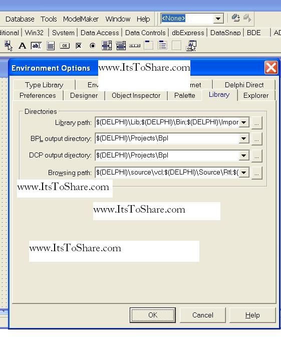
Back to Delphi , open page tool à environment option à click the library tab
Picture 6. Install Smallport / smport delphi : going to the smallport14 source path
Pointed the browsing path to  

 Picture 7. Install Smallport / smport delphi : Directing browsing path
After clicking the button in picture 7, it will appear dialog brain directories as follows:
Picture8.Install Smallport / smport delphi : dialog box directories
In picture 8, click the button which in the red circle, next is pointed to the directory C:\Program Files\Borland\Delphi7\Lib\smport14 then click OK, the picture is as follows:

Picture 9. Install Smallport / smport delphi : Pointing directory smallport14
Open component page  Install component:  
 
Picture 10. Install Smallport / smport delphi : Page Component.
Will appear as follow:  
Picture 11. Install Smallport / smport delphi : dialog box install component
In picture 11, click the browse button beside the Unit file name  
 
Picture 12. Install Smallport / smport delphi : Dialog box Unit File name 
in Picture 12 above, open folder smport14 the double click in smallport.pas
 Picture13. Install Smallport / smport delphi : Choose smallport.pas, 
will appear dialog box like the following below, then click OK

Picture 14. Install Smallport / smport delphi : Install the smallport componet
will appear dialog box as follows:
Picture 15. Install Smallport / smport delphi : Confirm Dialog box smallport componet installation

If the smallport component is successfully installed, then it will appear information box as follows
Picture 16. Install Smallport / smport delphi : Information box,
installation process is success
Then please open component pallete “system” you will find a component named Small Port that has been installed in that component pallete:

Picture 17. Install Smallport / smport delphi : Smallport component is Component Pallete “System”

 I hope this article can give benefit to the visitors, readers, developer and me. Thanks for visiting and availability for sharing this article by pressing 
Share this on Facebook
or just press like button under this posting

Wednesday, 24 August 2011

Controlling Electrical Equipment with 220 Volt Alternating Current (AC) With Delphi through Parallel Port Using Small Port Component.

Controlling Electrical Equipment with 220 Volt Alternating Current (AC) With Delphi through Parallel Port Using Small Port Component.

Basically, controlling electrical equipment 220 Volt Alternating Current (AC) with Delphi through parallel port using Small Port component has similarities with the article entitled controlling the Light Emitting Dioda (LED) flame with Delphi through parallel port which can be accessed CLICKHERE. The difference is on the Hardware which is used. In this case, the series is replaced with transistor series as electrical switch which able to activated and non-activated relay with 12 volt DC/220 volt AC. The series which able to replace LED is as follows:


Figure. Series  of  Controlling Electrical Equipment with 220 Volt Alternating Current (AC) With Delphi through Parallel Port Using Small Port Component.

The Component listed Below:


No Component Name
1 Dioda 1N 4001
2 Resistor 2,2K Ω
3 Transistor BC 107
4 Vcc 12 Volt DC


 I hope this article can give benefit to the visitors, readers, developer and me. Thanks for visiting and availability for sharing this article by pressing 
Share this on Facebook
or just press like button under this posting

Controlling The Light Emitting Dioda (LED) Flame With Delphi Through Parallel Port

Controlling The Light Emitting Dioda (LED) Flame With Delphi Through Parallel Port

Light Emitting Dioda (LED) is electronic component which able to change electrical energy into light energy. Basically, this component can be used as indicator that LED series is actively flowed current.
In this case, LED will have function as indicator in pin-pin LPT port which will be accessed through small port component in Delphi. If pin LPT port have logical 1 so LED will turn on, and vise versa, if the logical is 0 then LED will off, the series are as follows:


Figure. t he LED controller series through Parallel Port / LPT Port
 
Figure. The series of Controlling The Light Emitting Dioda through parallelport
The program which is used to control the LED is discussed in the writing entitled Accessing Parallel Port Personal Computer (LPT Port) with Borland Delphi 7.0 using Small Port component which can be accessed CLICKHERE.

 I hope this article can give benefit to the visitors, readers, developer and me. Thanks for visiting and availability for sharing this article by pressing 
Share this on Facebook
or just press like button under this posting

Accessing PC Parallel Port (LPT Port) With Borland Delphi 7.0 Using Small Port Component

Accessing PC Parallel Port (LPT Port) With Borland Delphi 7.0 Using Small Port Component

This article will lead you how to make a program to access input output data in parallel port, simple example, this program is used to turn on and turn of LED which is set in Parallel Port, Data Register in computer (Pin D2 until pin D9) in Parallel Port/ LPT.
The steps are as follows:
Enter the following component in Form 1:

No Component Property Value
1 Shape1 Name ShpLED1
Shape stCircle
Height 41
Width 41
Brush Color clWhite
Brush Style bsSolid
2 Shape2 Name ShpLED2
Shape stCircle
Height 41
Width 41
Brush Color clWhite
Brush Style bsSolid
3 Shape3 Name ShpLED3
Shape stCircle
Height 41
Width 41
Brush Color clWhite
Brush Style bsSolid
4 Shape4 Name ShpLED4
Shape stCircle
Height 41
Width 41
Brush Color clWhite
Brush Style bsSolid
5 Shape5 Name ShpLED5
Shape stCircle
Height 41
Width 41
Brush Color clWhite
Brush Style bsSolid
6 Shape6 Name ShpLED6
Shape stCircle
Height 41
Width 41
Brush Color clWhite
Brush Style bsSolid
7 Shape7 Name ShpLED7
Shape stCircle
Height 41
Width 41
Brush Color clWhite
Brush Style bsSolid
8 Shape8 Name ShpLED8
Shape stCircle
Height 41
Width 41
Brush Color clWhite
Brush Style bsSolid
9 EditText1 Name EdLED1
Text -
10 EditText2 Name EdLED2
Text -
11 EditText3 Name EdLED3
Text -
12 EditText4 Name EdLED4
Text -
13 EditText5 Name EdLED5
Text -
14 EditText6 Name EdLED6
Text -
15 EditText7 Name EdLED7
Text -
16 EditText8 Name EdLED8
Text -
17 Button1 Name BtnNyalaLED1
Caption NyalakanLED1
18 Button2 Name BtnNyalaLED2
Caption NyalakanLED2
19 Button3 Name BtnNyalaLED3
Caption NyalakanLED3
20 Button4 Name BtnNyalaLED4
Caption NyalakanLED4
21 Button5 Name BtnNyalaLED5
Caption NyalakanLED5
22 Button6 Name BtnNyalaLED6
Caption NyalakanLED6
23 Button7 Name BtnNyalaLED7
Caption NyalakanLED7
24 Button8 Name BtnNyalaLED8
Caption NyalakanLED8
25 Button9 Name BtnMatiLED1
Caption MatikanLED1
26 Button10 Name BtnMatiLED2
Caption MatikanLED2
27 Button11 Name BtnMatiLED3
Caption MatikanLED3
28 Button12 Name BtnMatiLED4
Caption MatikanLED4
29 Button13 Name BtnMatiLED5
Caption MatikanLED5
30 Button14 Name BtnMatiLED6
Caption MatikanLED6
31 Button15 Name BtnMatiLED7
Caption MatikanLED7
32 Button16 Name BtnMatiLED8
Caption MatikanLED8
33 Button17 Name BtnOpenPort
Caption Open Port
34 Button18 Name BtnClosePort
Caption CloseProgram
35 SmallPort1 Name SmPort1


In the monitor will appear image like the following;  
 
Picture1. Accessing PC Parallel Port (LPT Port) With Borland Delphi 7.0 Using Small Port Component : Visualization of the Program which will be made.
Before making listing program (source code) first we decide 2 variables which will be used; those are “data” and “NewData” which mean:
NO. NAMA KOMPONEN SOURCE CODE
1 BtnMatiLED1 data := SmPort1.ReadByte($378);
baru := data AND 254;
SmPort1.WriteByte($378,baru);
ShpLED1.Brush.Color := clBlack;
EdLED1.Text:='OFF';
2 BtnMatiLED2 data := SmPort1.ReadByte($378);
baru := data AND 253;
SmPort1.WriteByte($378,baru);
ShpLED2.Brush.Color := clBlack;
EdLED2.Text:='OFF';
3 BtnMatiLED3 data := SmPort1.ReadByte($378);
baru := data AND 251;
smport1.WriteByte($378,baru);
ShpLED3.Brush.Color := clBlack;
EdLED3.Text:='OFF';
4 BtnMatiLED4 data := SmPort1.ReadByte($378);
baru := data AND 247 ;
SmPort1.WriteByte($378,baru);
ShpLED4.Brush.Color := clBlack;
EdLED4.Text:='OFF';
5 BtnMatiLED5 data := SmPort1.ReadByte($378);
baru := data AND 239;
SmPort1.WriteByte($378,baru);
ShpLED5.Brush.Color := clBlack;
EdLED5.Text:='OFF';
6 BtnMatiLED6 data := SmPort1.ReadByte($378);
baru := data AND 223 ;
SmPort1.WriteByte($378,baru);
ShpLED6.Brush.Color := clBlack;
EdLED6.Text:='OFF';
7 BtnMatiLED7 data := SmPort1.ReadByte($378);
baru := data AND 191;
SmPort1.WriteByte($378,baru);
ShpLED7.Brush.Color := clBlack;
EdLED7.Text:='OFF';
8 BtnMatiLED8 data :=SmPort1.ReadByte($378);
baru := data AND 127;
SmPort1.WriteByte($378,baru);
ShpLED8.Brush.Color := clBlack;
EdLED8.Text:='OFF';
9 BtnNyalaLED1 data := SmPort1.ReadByte($378);
baru := data or 1;
SmPort1.WriteByte($378,baru);
ShpLED1.Brush.Color := clRED;
edLED1.Text:='ON';
10 BtnNyalaLED2 data := SmPort1.ReadByte($378);
baru := data or 2;
SmPort1.WriteByte($378,baru);
ShpLED2.Brush.Color := clRED;
edLED2.Text:='ON';
11 BtnNyalaLED3 data := SmPort1.ReadByte($378);
baru := data or 4;
SmPort1.WriteByte($378,baru);
ShpLED3.Brush.Color := clRED;
edLED3.Text:='ON';
12 BtnNyalaLED4 data := SmPort1.ReadByte($378);
baru := data or 8;
SmPort1.WriteByte($378,baru);
ShpLED4.Brush.Color := clRED;
edLED4.Text:='ON';
13 BtnNyalaLED5 data := SmPort1.ReadByte($378);
baru := data or 16;
SmPort1.WriteByte($378,baru);
ShpLED5.Brush.Color := clRED;
edLED5.Text:='ON'
14 BtnNyalaLED6 data := SmPort1.ReadByte($378);
baru := data or 32;
SmPort1.WriteByte($378,baru);
ShpLED6.Brush.Color := clRED;
edLED6.Text:='ON';
15 BtnNyalaLED7 data := SmPort1.ReadByte($378);
baru := data or 64;
SmPort1.WriteByte($378,baru);
ShpLED7.Brush.Color := clRED;
edLED7.Text:='ON';
16 BtnNyalaLED8 data := SmPort1.ReadByte($378);
baru := data or 128;
SmPort1.WriteByte($378,baru);
ShpLED8.Brush.Color := clRED;
edLED8.Text:='ON';
17 BtnOpenPort SmPort1.Opened:=true;
18 BtnCloseProgram Close;
            “Data” is value that will be read from parallel port in the form of 8 bit data (1 byte)
“New data” is value that will be written to the parallel port after conducted

“Modification” with logical “and” or “or” to conduct bit setting or bit clearing data which is written in the form of 8 bit data (1 byte)
Variable writing decision is conducted under the writing:
var
Form 1:Tform1;
The result is as follows: 
Picture 2. Accessing PC Parallel Port (LPT Port) With Borland Delphi 7.0 Using Small Port Component : variable declaration
The next step is how to make source code program comprehensively so that the program can be used:
Type source code below, appropriate with each component which mean:


result of program execution is like this:  


Picture 3. Accessing PC Parallel Port (LPT Port) With Borland Delphi 7.0 Using Small Port Component : The Result of Program Execution.

 I hope this writing can give benefit to the visitors, readers, developer and me. Thanks for visiting and availability for sharing this article by pressing Share To Facebook, Twitter button or just press like button.