Showing posts with label Serial Communication Delphi. Show all posts
Sunday, 30 December 2012
Friday, 28 October 2011
Serial Communication Delphi
| October 28, 2011
Using Hyperterminal for Serial Communication Delphi
this is the test of Serial Data Sender on Microcontroller by Using Bascom Code on Microcontroller AT-MEGA 16 (posted before this article)
The program can be interfaced with PC by using HyperTerminal. To open Hyper Terminal can be done as follows:
1. Start à Program à Accessories à Communications à Hyper Terminal
Picture. Starting Hyper Terminal
2. Putting name on connection description, the name can be filled by everything, for example “serial comm”
Picture. Putting Connection Name of Hyper Terminal
3. Press button OK, then it will appear connect to arrangement. On menu connect using, choose COM 1 like the picture below:
Picture. Choosing Port Com
4. After that, press button OK like the picture below
Picture. Choosing COM 1
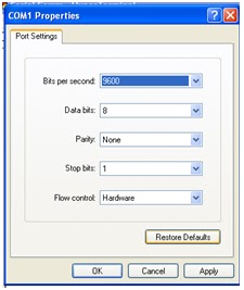
5. Set Baudrate (bits per second), data bits, etc. It can be seen through the picture below
Picture. Setting Rate Baud Property
6. Press Button OK, so that Hyper Terminal is ready to receive data. Afterwards, connect port serial (DB9) to PC with serial communication pin on microcontroller. Here is the result of program testing on microcontroller used.
Picture. Serial Communication Testing with Hyper Terminal
Serial Communication Delphi
| October 28, 2011
Serial Data Sender Program Listing on Microcontroller by Using Bascom Code on Microcontroller AT-MEGA 16 (in order to create an serial communication to delphi)
Table. The Example of Serial Communication Program
Source Code | A Brief Explanation |
$Regfile=”m16def.dat” | A type of microcontroller used |
$Crystal=16000000 | Crystal which is used |
$Baud=19200 | Baud Rate which is used |
Print “Test Serial” | Writing text test serial to PC, the next between mark “ “ |
End | The end of source code |
![]() |
| serial communication delphi with mirocontroller bascom |
Picture. The Example of Serial Communication Program AT MEGA 16 with Bascom AVR
Afterwards, the program can be compiled, and then it is downloaded to microcontroller with extreme burner software.
the testing of this applcation can be checked on the post Using Hyperterminal for Serial Communication Delphi
Serial Communication Delphi
| October 28, 2011
Serial Data Sender on Microcontroller by Using Bascom Code on Microcontroller AT-MEGA 16 (in order to create an serial communication to delphi)
Before program writing that will be downloaded to microcontroller, it needs two additional software: Bascom AVR and Extreme Burner, both demo versions of each software have been included into CD bundle. Bascom AVR has function as software writer to write source code microcontroller programming and compiling process. While extreme burner has a function as source code downloader that has been written by Bascom AVR, then compiling.
Basically, serial communication on AT MEGA 16 with Bascom AVR is easy and simple. It is only conducted by determining baudrate grade used in serial communication. It can be conducted through two ways:
1. Setting on compiler, option àcompiler à communication
Afterwards, input baudrate grade and appropriate frequency
2. Determining manually assembler directive on program created, for example:
$ Crystal= 16000000
$ Baud= 9600
The second way is the way which is used as material for serial data sending practice on AVR-AT MEGA 16
Thursday, 27 October 2011
Serial Communication Delphi
| October 27, 2011
Port Serial
| serial port |
Port Serial
Standard RS 232 was established by Electronic Industry Association and Telecommunication Industry Association in 1962. The complete name is EIA/TIA-232 interface between Data Terminal Equipment and Data Circuit-Terminating Equipment Employing Serial Binary Data Interchange. In spite of its long name, this standard only relates to data communication between computers with computer complement equipment. There are two main stuffs set by standard RS 232, i.e:
Ø Signal form and tension level used RS 232 was created in 1962, before ICTTL was well-known. Moreover, the tension level determined for RS 232 does not have any relation with the level TTL, even it is said that it is different. Here are differences between the tension level RS 232 and TTL:
Picture. Differences between the Tension Level RS232 and TTL
Ø Determination of signal types and connector used, and signal structure in connector foot 9. Some parameters determined by EIA (Electronic Industry Association) are
1. Space (logic 0) tension from +3 V to +25 V
2. Mark (logic 1) tension from -3 V to -25 V
3. Tension area from +3 to -3 V is not defined
4. Open series tension must not more than 25 V (ground reference)
5. Short connective series current must not more than 500 Ma
A driver has to be able to handle this current without getting broken. Beside describing the tension level like what it has been discussed above, Standard RS232 determines signal types used to arrange information exchange between DTE and DCE.
There are 24 signal types. However, common signal used are usually 9 signal types. Connector used is determined in standard RS 232, for complete signal used by connector DB 25. While connector DB 9 is only used for 9 signals which is commonly used
TD | Transmit Data | For sending serial data |
RD | Received Data | For receiving serial data |
RTS | Request to Send | A signal for informing modem that UART is ready to conduct data exchange |
CTS | Clear to Send | Telling that modem is ready to conduct data exchange |
DSR | Data Set Ready | For telling UART that modem is ready to conduct data exchange |
CD | Carrier Detect | While modem detect “carrier” from other modem, the signal will be activated |
DT | Data Terminal | The opposite of DSR, it is used for telling that UART is ready to conduct communication |
R | Ready | For telling that UART is ready to conduct communication |
RI | Ring Indicator | It will be active if modem detects quivering signal from phone channel |
Those signals 96 are in the direction of DCE and come from DCE. For the signals in the direction of DCE, it means that DTE has function as output and input, for example signal TxD, at the side of foot DTE TxD is output. This foot is connected to foot TxD on DCE which has a function as input. The other way around of TxD signal is RxD. This signal comes from DCE and it is connected to RxD foot on DTE which has a function as output.
Testing conducted by connecting two computers through port serial (port DB 9) is with null modem configuration. Null modem configuration is conducted with 3 data channel: TxD (sending channel), RxD (receiving channel), and ground.
Basically, serial communication inter PC occurs through port serial or DB9. Powerful component which can be used for accessing/serial communication for Delphi is comport. In creating the application of serial communication between two personal computers (PC), it needs two applications, i.e: data sender application and data receiver application. The application that will be created recently is simple application which can be then developed to be more complex application.
Serial Communication Delphi
| October 27, 2011
Serial Communication
| RS232 for serial communication |
Serial Communication
If any data parallel port with certain bit is sent simultaneously at one click, data serial port is sent one by one per one bit. The weakness of sending data by serial is that it is more complex rather than by interface parallel port. It is because the data is sent per bit in series, so that the data sending occurs slowly. Nevertheless, this condition can be overcome by high Bard Rate on data sending. Meanwhile, the strengths are:
1. Cable for serial communication can be longer than parallel, the data in serial communication is sent for logic ‘1’ as tension -3 to -25 volt and for logic ‘0’ as tension +3 to +25 volt. Therefore, the tension in serial communication has maximum tension handle 50 volt. Whereas in parallel communication, it is only 5 volt. This case causes disturbance on long cables which is easier to overcome than parallel one.
2. The number of serial cable needed is less than parallel one. You can connect two sets of computer equipment with only three cables to configure null modem, TxD (sending channel), RxD (receiving channel) and ground. Imagine! If it uses parallel technique, there will be 20-15 cables! However, in each computer with serial has to spend much more cost, for interface serial is more expensive than parallel one.
3. Almost all equipments (palmtop, organizer, mobile phone, etc) recently use infra-red technology for data communication. In this context, data sending is conducted by serial IrDA-1 (the first infra-red specification) is able to send data in 115,2 kbps in speed and it is assisted by UART equipment. The charge length decrease 3/16 from standard RS-232 to economize the power
4. For embadded system technology, there are a lot of microcontrollers completed with serial communication (both RISC and CISC) or serial communication interface (SCI). With the existing of integrated SCI on IC microcontroller, it will decrease the number of an output pin. Furthermore, it only needs 2 main pins : TxD and RxD (out of ground reference)
Data frame on sending serial data AVR AT mega 16 can be viewed through the picture below:
Picture. The Frame of Sending Serial Data for Letter A
In the condition without data (idle), signal is in a high logic. When data is started to send, it will begin by giving start bit signal (St) with low logic as initial sign of data sending, followed by data that is sent (5, 6, 7, 8, or 9 bit). Bit parity has optional character. At last, it is added by stop bit (Sb) which is 1 or 2 bit in number.
Additional Note:
Serial communication between PC and microcontroller can not occur direct by connecting pin Tx on PC with pin Rx on microcontroller and Rx on PC with pin Tx on microcontroller, and pin ground on PC with pin ground on microcontroller.
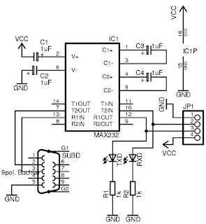
The level of work tension on serial communication on microcontroller is TTL (0-5 volt). Meanwhile, the level of work tension in PC serial port is from +15 V to -15 V. It happens because there is difference between tension level used for PC serial communication and microcontroller. The level of serial communication tension on microcontroller has to be adjusted with the level of serial communication tension on PC. To do that, it needs the series of converter RS 232. The series picture can be seen as follows:
Picture. Schematic of Converter Series RS 232
Friday, 23 September 2011
Serial Communication Delphi
| September 23, 2011
Download Cport/Comport for Serial Communication Delphi
Cport or Comport is a free component that can support serial communication in delphi, for example : accessing sms on mobile phone, accessing data from serial port/ DB9 Port, Accessing data from serial port Microcontroller etc, you also can use this component for accessing data from multi channel ADC microcontroller (e.g : ATMega 8535 or ATMega 16)
CLICK HERE TO DOWNLOAD Cport/Comport Component For DELPHI
I hope this article can give benefit to the visitors, readers, developer and me. Thanks for visiting and availability for sharing this article by pressing
| Share this on Facebook |